Large Capacity Flotation Machine in Mineral Processing Plant 15kw
Flotation Machine Application
Flotation machine (also called Flotation separator) is applicable for the separation of nonferrous metal and ferrous metal and nonmetal, such as fluorite and talc. The impeller is driven by V-belts, which can bring the centrifugal effect to form the negative pressure. On the one hand, to inhale sufficient air to mix with ore pulp; on the other hand, to stir ore pulp and mix with medication to form the mineralized froth. By adjusting the height of flashboard you can control the liquid level and make the useful froth scraped by loam board.
Flotation Machine Working Principle
When flotation machine works, slurry is inhaled from the bottom of the trough to the space between impellers. Meanwhile, the low pressure air sent by fan is sent to this area through the air distributor in the hollow shaft. After sufficient mixing, the slurry is pushed out by the impeller, and then goes to the whole trough. When the froth rises to the stable level, after the enrichment processing, froth overflows to the froth trough from the overflow weir. Another part of ore slurry flows to lower part of impeller for the remixing with air. The remaining slurry flows to the next trough until it becomes residue.
Technical Parameters:
SF series Flotation Machine
| Model | Cell volume(m³) | Impeller diameter (mm) | Impeller speed (r/min) | Capacity (m³/min) | Main motor power (kW) | Scraper motor power (kW) | Weight (t/cell) |
| SF0.37 | 0.37 | 300 | 442 | 0.2-0.4 | 1.5 | 1.1 | 0.4 |
| SF0.7 | 0.7 | 350 | 400 | 0.3-1 | 3 | 1.1 | 0.9 |
| SF1.2 | 1.2 | 450 | 312 | 0.6-1.2 | 5.5 | 1.1 | 1.4 |
| SF2.8 | 2.8 | 550 | 268 | 1.5-3.5 | 11 | 1.1 | 2.2 |
| SF4 | 4 | 650 | 235 | 2-4 | 15 | 1.5 | 2.6 |
| SF8 | 8 | 760 | 191 | 4-8 | 30 | 1.5 | 4.3 |
| SF16 | 16 | 850 | 190 | 5-16 | 45 | 1.5 | 7.4 |
BF series Flotation Machine
| Model | Cell volume(m³) | Impeller diameter (mm) | Impeller speed (r/min) | Air inflow (m³/m2.min) | Capacity (m³/min) | Power (kW) | Weight (t/cell) |
| BF2.8 | 2.8 | 550 | 278 | 0.9-1.1 | 1.4-3 | 11 | 2.1 |
| BF4 | 4 | 650 | 235 | 0.9-1.1 | 2.4-4 | 15 | 2.6 |
| BF6 | 6 | 700 | 205 | 0.9-1.1 | 3-6 | 18.5 | 3.3 |
| BF8 | 8 | 760 | 188 | 0.9-1.1 | 4-8 | 22 | 4.1 |
| BF10 | 10 | 760 | 188 | 0.9-1.1 | 5-10 | 22 | 4.5 |
| BF16 | 16 | 850 | 195 | 0.9-1.1 | 8-16 | 37 | 8.3 |
| BF20 | 20 | 850 | 195 | 0.9-1.1 | 10-20 | 45 | 8.7 |
| BF24 | 24 | 920 | 181 | 0.9-1.1 | 12-24 | 45 | 9 |
KYF series Inflatable Flotation Machine
| Model | Cell volume(m³) | Impeller diameter (mm) | Impeller speed (r/min) | Air pressure of air blower (kPa) | Max. Air inflow (m3/m2.min) | Capacity (m3/min) | Main motor power (kW) | Scraper motor power (kW) | Weight (t/cell) |
| KYF1 | 1 | 340 | 281 | ≥12.6 | 2 | 0. 2-1 | 4 | 1. 1 | 0. 8 |
| KYF2 | 2 | 410 | 247 | ≥14.7 | 2 | 0. 4-2 | 5. 5 | 1. 1 | 1. 5 |
| KYF3 | 3 | 480 | 219 | ≥19.8 | 2 | 0. 6-3 | 7. 5 | 1. 5 | 1. 9 |
| KYF4 | 4 | 550 | 200 | ≥19.8 | 2 | 1. 2-4 | 11 | 1. 5 | 2. 2 |
| KYF8 | 8 | 630 | 175 | ≥21.6 | 2 | 3. 0-8 | 15 | 1. 5 | 4. 2 |
| KYF16 | 16 | 740 | 160 | ≥25.5 | 2 | 4. 0-16 | 30 | 1. 5 | 6 |
| KYF24 | 24 | 800 | 150 | ≥30.4 | 2 | 4. 0-24 | 30 | 1. 5 | 7. 5 |
| KYF38 | 38 | 880 | 138 | ≥34.3 | 2 | 10-38 | 37 | 1. 5 | 10. 3 |
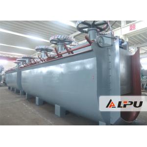
Flotation Machine Displayed in Our Factory: